Monocrystalline Premium 250W

PV-MLT250HC

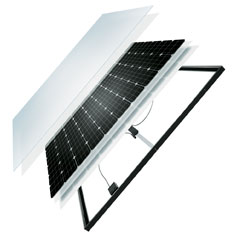
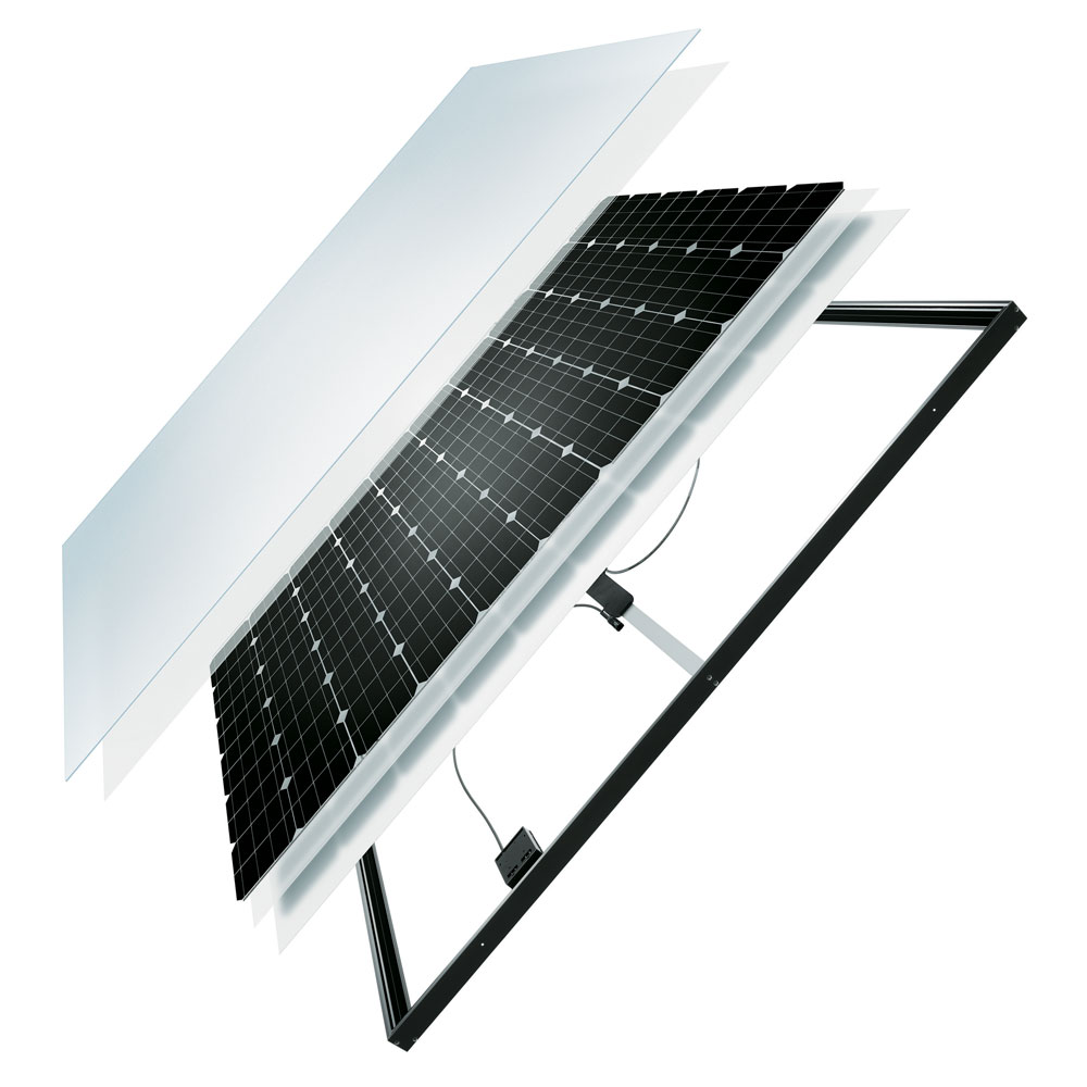
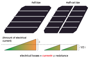
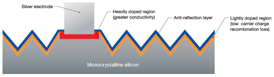
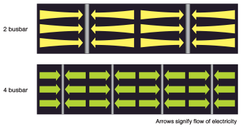
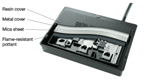
The technology and design of our product incorporates our comprehensive experience and extensive know-how in creating photovoltaic modules. The Mitsubishi Electric difference lies in all of the small details that add up for outstanding performance, reliability, and safety.

Discontinued Product

Features

Superior Technology

Half-cut Cell

By reducing the area of each cell and connecting them in a parallel formation, the amount of electrical current carried by each busbar is reduced by half. This results in the decrease of electrical resistance within the busbars and an increase in overall efficiency of about 2.5%.

Cells are cut with a special process using a high-precision laser to maintain the integrity of the cell.

By using half-cut cells, the electrical current ( i ) flowing in each busbar is halved. Therefore, the amount of internal losses in a half-cut module is 1/4 of a full sized cell module.

Selective Emitter

In a standard doping process, silicon wafers are doped with phosphorus to create a P/N junction. The level of doping concentration was a trade-off between conductivity with the cell electrodes and carrier charge recombination. Higher concentration levels leads to higher conductivity, but more carrier charge losses, and vice versa. As a solution, Mitsubishi Electric has introduced a new selective emitter process in which only the area in contact with the electrodes is doped with high concentrations to maintain both high conductivity and low carrier charge losses. This improvement has resulted in an increase in cell output of approximately 5%

4 Busbar Cell

Through an industry-leading innovation of integrating 4 busbars into each cell, internal electrical resistance is reduced, boosting cell output by 3%*. This is possible because the distances between the busbars are shorter and less current flows through each smaller electrode where resistance is the highest.

*Approximate improvement compared to a standard 2 busbar cell.

Newly Re-designed Junction Box

Our field-proven high safety junction box has been re-designed and optimized for use with monocrystalline cells. As one of the most critical parts of the module in terms of safety, our junction box features a waterproof, flame-resistant 4 layer barrier of protection. Combined with highly heat-resistant diodes, efficient heat-sink, and secured intertwining tab connections, our junction boxes boast a top-class level of safety.

Anti-reflective Glass

An anti-reflective coating has been added to the glass of our modules. It improves the light transmittance of the glass by reducing the amount of reflection on the surface. This improvement has led to a module output increase of 2%. Furthermore, Mitsubishi Electric modules use a non-porous type of anti-reflective coating, which is more resistant to the adhesion of dust than porous types.

Lead-free Solder

Mitsubishi Electric was the first Japanese manufacture to introduce (and still use) 100% lead-free solder in the inter-cell connections as another initiative contributing to environmental protection.

Reliable in New Zealand Conditions

Improved Frame

Our classic hollowless L-frame design has been improved with a smarter protection bar insert. As a result, the strength of the new frame has increased by approximately double that of the previous L-frame. In addition, modules can now be installed by clipping the shorter sides, simplifying system design and installation.

Double Corrosion-resistant Frame Coating

The highly durable aluminum frame is treated with two separate corrosion-resistant coatings for excellent durability and a beautiful finish. Even the individual screws have double anti-corrosive coatings for lasting protection.

High Snow Load

Our modules have been designed to withstand harsh environmental conditions, such as in areas with high snowfall. The high structural strength of the modules has passed the IEC 61215 static loading test at 5400Pa.

Installable in Areas with High Salt Concentration

Normally, high salt content in the air (in areas such as next to the ocean) can do serious damage to the structural integrity of a PV module, and can also pose an electrical safety hazard by causing corrosion. However, due to the intelligent design and high quality of the materials used, our modules can be safely installed in such areas with high salt concentration in the air*.

*Excluding areas in which the module comes into direct contact with salt water.

The frame and laminate are designed so that a stong physical and electrical barrier is maintained even in harsh environments.

Specifications

Cell type: Monocrystalline silicon, 78mm × 156mm
Number of cells: 120 cells
Performance at STC
Maximum power rating (Pmax): 250W
Warranted minimum Pmax: 242.5W
Tolerance of Pmax: +/-3% (The average Pmax of each pair of modules has a positive tolerance)
Open circuit voltage (Voc): 37.6V
Short circuit current (Isc): 8.79A
Maximum power voltage (Vmp): 31.0V
Maximum power current (Imp): 8.08A
Performance at NOCT*
Maximum power rating (Pmax): 180W
Open circuit voltage (Voc): 34.2V
Short circuit current (Isc): 7.12A
Maximum power voltage (Vmp): 27.9V
Maximum power current (Imp): 6.46A
Normal operating cell temperature (NOCT): 47°C
Maximum system voltage: 1000V
Fuse rating: 15A
Dimensions: 1625×1019×46mm (64.0×40.1×1.81inches)
Weight: 20kg (44lbs.)
Output terminal: (+) 800mm/(-) 1250mm with MC connector (PV-KTB4/6II-UR, PV-KST4/6II-UR) Cable conforms with TÜV Specification 2 PfG 1169/08.2007
Module efficiency: 15.1%
Packing condition: 2 pcs / 1 carton
Certificates: IEC 61215 Second Edition, IEC 61730
Product Warranty: 10 years
Output Warranty: 90% of rated minimum Pmax for 10 years 80% of rated minimum Pmax for 25 years
Notes
*: Measured at 800w/m2, ambient temp. 20°C, wind speed 1m/ s

Dimensions

Note: Dimension unit (mm).

Support

*Actual price may differ.